
Inverter schematics and photos are of the orriginal design tested on 600w load with great success.
 Schematic diagram.
 Wiring of transformer
Control circuit.
 Front pannel.
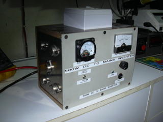 Side view.
Inverter powered on.
Voltage input:12v dc
Voltage out:220 v ac
Frequency:50hz/60hz
Power:500w
Designed and constructed by Roderick bonello.
posted by enlightened at 9:03 AM
![]()

5 Comments:
well the transistors are mounted five on each heatsink.as you have two squarewaves functioning as a push pull circuit and are used as the sides of the units.the heatsinks are also the output of the transistors connected to the end tappings of the transformer.
i'm already to test the 500 w inverter but the transformer output is 25 Vac. Why the inverter output not 220 Vac? what's wrong in teh circuit?
please give me know. and email to me at down_mp3@yahoo.com
Dear Roderick,
I'm really interested in making the 500w inverter u modified and built.Though most of the part of the schematic that u posted is clear some parts like the part just left of the 7812 is not clearly visible(the value that is)so can u please mail me a better quality of that schematic.Also can u suggest on the substitutes for 0.1uF metalized-film capacitor(wont ceramic do?) and 2sc1061.
Thank you,
Regards,
Kaushal
kkumar28@gmail.com
pls send to me the parts list components 500w power inverter because some compunet value are not clear at the pictures tnx
hi can you tell me about your transformer current ? is it 10a or more ?
Thanks
Post a Comment
<< Home